Following steps give detailed explanations on how to put everything together as well as showing you how to use our scripts and tools provided.
Quicklinks to all steps:
- Step 1: Assembling the Banana Pis
- Step 2: Preparing the Storage
- Step 3: Connecting all Devices
- Step 4: Configuring the Gateway
- Step 5: Scripts and Configurations
- Step 6: Monitoring and Logging
- Step 7: Managing the realtime-logging daemon
Step 1: Assembling the Banana Pis
In this step you should make sure that your routers will be protected from harm during the network simulations to come. Whether you chose to acquire R1CASEs or you are using another solution – always verify that your USB charger cables fit (see possible problems with R1CASE in Hardware Requirements page). We strongly suggest labeling your devices so you can always distinguish between them, for example we started out labeling from the number 10 as the Pis in our management network use the fixed IPs 192.168.0.10 to 192.168.0.29 and in the emulation network 192.168.1.10 to 192.168.1.29 respectively. As you will have to configure each Pi manually you are free to choose which number you start out labeling from, but keep in mind that they should resemble the IPs you later assign to them in order to avoid confusion.
Step 2: Preparing the Storage
In this step you prepare the microSDs and the SSDs for duty. You will need the images from our Download section before proceeding. However you want to mount your storage and transfer the images is your choice – this section will describe how to do it in a standard Linux distribution (e.g. Ubuntu). Therefore it will further on be assumed you have set up a PC using Linux and you possess administrative rights.
After hooking up your micro SD card or SSD to your PC you should first carefully check which device name Linux assigned to your new storage. This can be achieved by opening a new Terminal and entering following command:
sudo fdisk -l
You will see a detailed list of storage devices currently attached – their names will resemble /dev/sdx, where x starts out at ‘a’, then ‘b’, then ‘c’, etc. Thus if your PC for example contains one hard disk (no matter the amount of partitions) it will get the device name /dev/sda and an additional SD card very likely will receive /dev/sdb. Because this is most common we will continue to refer to your mounted device as /dev/sdb but again: please examine this carefully as you can really damage you system if you transfer either image onto the wrong disk.
The disk dump command (dd) can be used to transfer the images onto the devices and also vice-versa to create your custom image, should you choose to adjust ours. To speed up the copying process it pays off to consider adjusting the transfer block size. The optimal size is hard to determine, because it is hardware and OS dependent, but almost always greater than the default 512 Bytes used by dd. We chose 64K as this seemed to be a good trade-off according to several sources relying on this experiment. Therefore the Terminal command we used to transfer or create images is (substitute ‘image.img’ with the path and name of the extracted image):
dd if=image.img of=/dev/sdb bs=64K
The progress of this transfer can be monitored by opening another Terminal and entering:
watch -n5 'sudo kill -USR1 $(pgrep ^dd)'
You can prepare all micro SDs as they only contain the bootloader needed to start up the device, hence they will not change unless you recompile the Bananian kernel. However, regarding the SSDs we advise you to only prepare one or a few initially and only continue to prepare all if you are sure that all configurations fit your needs – please refer to the Scripts and Configurations section below for a better overview and instructions on how to alter settings.
Now the individual IPs of the Banana Pi Routers need to be configured. For this the devices need to be accessed while running, so either you plug in a keyboard and a monitor or you attach it to your PC via a patch cable.
In case you choose to connect via a patch cable, you will have to use the rightmost (closest to the HDMI slot) network port and configure it to be part of the 192.168.0.x network (e.g. 192.168.0.1 for interface eth0).
After restoring the pi_ssd_image on a Banana Pi, the default IP will be 192.168.0.30.
sudo ifconfig eth0 192.168.0.1
ssh nfd@192.168.0.30
In case you choose to work directly on the Pi using a connected keyboard and monitor, wait for it to boot and login with a user name and a password – you can choose between the following:
- Administrator: u: root p: pi
- NFD user: u: nfd p: nfd
You should now see the command prompt. The default keyboard layout is en/us, therefore if you need to change it to a different one use ‘sudo loadkeys keymap’ (e.g. ‘sudo loadkeys de’, complete list here). Now open ‘/etc/network/interfaces’:
sudo vi /etc/network/interfaces
You should see an equivalent output to the following:
# interfaces(5) file used by ifup(8) and ifdown(8)
auto lo
iface lo inet loopback

# static ip management NW
auto eth0.101
iface eth0.101 inet static
        address 192.168.0.10
        netmask 255.255.255.0
        gateway 192.168.0.1

# static ip simulation NW
auto eth0.102
iface eth0.102 inet static
        address 192.168.1.10
        netmask 255.255.255.0
Note that this configuration step cannot be automated because hooking up all Pis to a switch using the same image, i.e. giving them the same IP, will of course only result in address conflicts.
Step 3: Connecting all Devices
Connecting your Banana Pis to your switches is straightforward – a good strategy is to use the same port number per Pi on both management and emulation switch x proceeding in the following fashion: Pi number 1 connects to port 1 of both switches, Pi number 2 to port 2, Pi number 3 to port 3, …
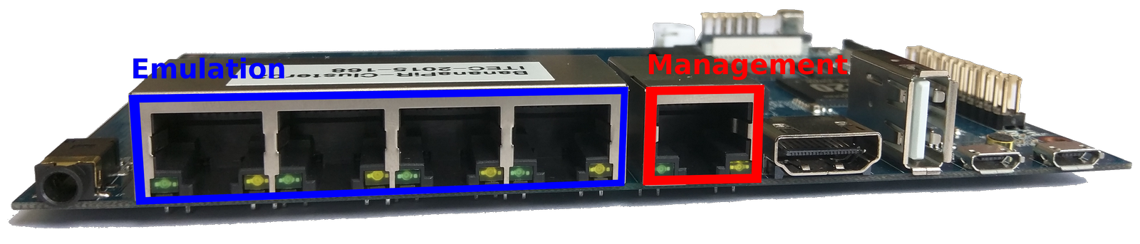
Whereas you are free to choose how you connect the devices to the switches, plugging your management and emulation cables into a Banana Pi Router must be done in a specific way: connect one network to the separate port (next to the HDMI out) and the other to one of the four remaining ports. The picture below again shows an assembly suggestion.
This mandatory step is due to the configurations we made to the Bananian image, splitting the five ports into 2 virtual ports. This configuration of course can be changed by altering the ‘/etc/network/if-pre-up.d/swconfig’ file (the comments in the file provide good documentation on how to do this). If you decide to reconfigure the ports you will also have to adjust the network configuration file (‘/etc/network/interfaces’) to match your modified VLAN ports. In any case, should you choose to alter configurations on the Banana Pi image, please remember to do it BEFORE putting the image on all of your SSD drives as either alternative (transferring the image again or reconfiguring all Pis separately) will be tedious work.
Step 4: Configuring the Gateway
The Gateway, as already mentioned, connects the management network to an outside network, e.g. your intranet. It needs to have two network cards to be part of both networks. This setup enables all users to securely access the management network, makes collecting logging information from the Banana Pis easier and optionally provides the devices with an internet connection.
We used a standard desktop with Ubuntu 14.04 and configured one ethernet card to be part of the management network by again editing ‘/etc/network/interfaces’:
# interfaces(5) file used by ifup(8) and ifdown(8)
auto lo
iface lo inet loopback

auto eth2
iface eth2 inet static
address 192.168.0.1
netmask 255.255.255.0
Note that ‘192.168.0.1’ resembles the standard gateway configured in our SSD image – if you plan to use a different address here, you will as well have to edit the interfaces file on the image. The other network card is set up to automatically receive an IP from our intranet via DHCP.
If you want your Pis to be able to access the internet please read on, otherwise you can skip to the next section.
First you need to enable IP forwarding by editing ‘/etc/sysctl.conf’ (remove the comment before following line):
# Uncomment the next line to enable packet forwarding for IPv4
net.ipv4.ip_forward=1
Doing the above does not enable the gateway to do NAT for the individual Pis. To fix this a script has to be created (source) and executed during boot time (Make sure EXTIF matches your external network interface – here eth1 – and INTIF matches your internal network interface – here eth2). Save following script to nat.sh:
echo -e "\n\nLoading simple rc.firewall-iptables version $FWVER.."
echo -e "\n"
DEPMOD=/sbin/depmod
MODPROBE=/sbin/modprobe

EXTIF="eth1"
INTIF="eth2"
#INTIF2="eth0"
echo " External Interface: $EXTIF"
echo " Internal Interface: $INTIF"

#=================================================================
#== No editing beyond this line is required for initial MASQ tests
echo -en " loading modules: "
echo " - Verifying that all kernel modules are ok"
$DEPMOD -a
echo "------------------------------------------------------------"
echo -en "ip_tables, "
$MODPROBE ip_tables
echo -en "nf_conntrack, "
$MODPROBE nf_conntrack
echo -en "nf_conntrack_ftp, "
$MODPROBE nf_conntrack_ftp
echo -en "nf_conntrack_irc, "
$MODPROBE nf_conntrack_irc
echo -en "iptable_nat, "
$MODPROBE iptable_nat
echo -en "nf_nat_ftp, "
$MODPROBE nf_nat_ftp
echo "------------------------------------------------------------"
echo -e " Done loading modules.\n"
echo " Enabling forwarding.."
echo "1" > /proc/sys/net/ipv4/ip_forward
echo " Enabling DynamicAddr.."
echo "1" > /proc/sys/net/ipv4/ip_dynaddr
echo " Clearing any existing rules and setting default policy.."

iptables-restore <<-EOF
*nat
-A POSTROUTING -o "$EXTIF" -j MASQUERADE
COMMIT
*filter
:INPUT ACCEPT [0:0]
:FORWARD DROP [0:0]
:OUTPUT ACCEPT [0:0]
-A FORWARD -i "$EXTIF" -o "$INTIF" -m conntrack --ctstate \
ESTABLISHED,RELATED -j ACCEPT
-A FORWARD -i "$INTIF" -o "$EXTIF" -j ACCEPT
-A FORWARD -j LOG
COMMIT
EOF

echo -e "\nrc.firewall-iptables v$FWVER done.\n"
After configuring the 2 variables and saving the script as nat.sh, make it executable by doing:
chmod a+x nat.sh
Now test the script by running it as root:
sudo sh nat.sh
Investigate the messages from the console output to see if any error occurred. If everything looks fine, you can try to ping the Google DNS server from a Banana Pi Router (connect via ssh, e.g. ‘ssh nfd@192.168.0.10’):
ping -c 3 -W 10 8.8.8.8
If ping responds, make the new script bootable so you don’t have to run the script every time you restart:
sudo cp nat.sh /etc/init.d/
sudo ln -s /etc/init.d/nat.sh /etc/rc2.d/S95masquradescript
Since the Pis are configured to use the gateway as DNS server, it needs to be a Nameserver-Forwarder for DNS resolution to work properly – simply install ‘dnsmasq’ on the gateway to achieve this:
sudo apt-get install dnsmasq
As a final test, restart your computer and test if everything works correctly. Since DNS resolution should work now, you can ping using Google’s domain name from a Pi:
ping -c 3 -W 10 www.google.com
Step 5: Scripts and Configurations
This section contains information on how to configure the Pis’ emulation network via the management network. Most of the scripts we use are available in the Download section.
Configuring routes via iptables
The tools ‘iptables’ / ‘ip6tables’ are used to conduct IPv4 / IPv6 packet filtering and NAT. There are five tables that offer different functionalities to the user. For our purposes, however, the default filtering table suffices. The filtering table possesses three built-in chains, which need to be configured for routing between the Pis: INPUT, FORWARD and OUTPUT. A per-simulation generated list determines all virtual connections between the individual routers and to configure a single connection between two routers (e.g. 192.168.1.11 & 192.168.1.13) following steps are necessary:
- Change the default policy to drop all packets on all chains (do this for both routers):
sudo iptables -P INPUT DROP
sudo iptables -P FORWARD DROP
sudo iptables -P OUTPUT DROP
- Allow traffic to other router (here on 192.168.1.11 using 192.168.1.13, also has to be done for 192.168.1.13 using 192.168.1.11):
sudo iptables -A INPUT -s 192.168.1.13 -j ACCEPT
sudo iptables -A INPUT -d 192.168.1.13 -j ACCEPT
sudo iptables -A FORWARD -s 192.168.1.13 -j ACCEPT
sudo iptables -A FORWARD -d 192.168.1.13 -j ACCEPT
sudo iptables -A OUTPUT -s 192.168.1.13 -j ACCEPT
sudo iptables -A OUTPUT -d 192.168.1.13 -j ACCEPT
Shaping traffic via tc
For simulation also traffic shaping is considered. Therefore also different link speeds are generated and added to the list with virtual Pi connections. The Linux traffic control tool (‘tc’) is used to assign the different bandwidths to the links. Following steps describe how to define the link bandwidth between nodes:
- Delete all previously set rules:
tc qdisc del dev eth0 root
- Create default link speed of 100 Mbit:
tc qdisc add dev eth0 root handle 1: htb default 10
tc class add dev eth0 parent 1: classid 1:10 htb rate 100mbit ceil 100mbit
- Create separate up- / download link speeds (2000 kbit / 4000 kbit) for a specific Pi (IP: 192.168.0.10, class based queueing via hierarchical token bucket):
tc class add dev eth0 parent 1: classid 11 htb rate 2000 kbit
tc class add dev eth0 parent 1: classid 21 htb rate 4000 kbit
tc filter add dev eth0 protocol ip parent 1:0 prio 1 u32 \
   match ip src 192.168.0.10 match ip dst 192.168.0.11 flowid 11
tc filter add dev eth0 protocol ip parent 1:0 prio 1 u32 \
   match ip src 192.168.0.11 match ip dst 192.168.0.10 flowid 21
- An equivalent configuration needs of course as well be employed on the second Pi router interconnected by this link. In this case this link 2 is 192.168.0.11, therefore only the ‘src’ and ‘dst’ IPs would have to be swapped.
Note: Traffic control (‘tc’) was at the time we built our network not part of the original Bananian distribution and we had to recompile the kernel to enable it – see how to here.
Step 6: Monitoring and Logging
In this step you install a basic overview/monitoring-webpage on the gateway-server.
Monitoring and logging are important aspects of the work with the Banana Pi routers, they enable users to track events, power consumption, resource utilization, etc.
Basic logging has been set up on the Banana Pi Routers, and the gateway can be configured to show the resulting statistics.
By default the Routers will be running a cron job, which logs the device’s current status and hosts it via lighttpd service. The gateway can collect all these periodical logs and host the collected statistics for all Banana Pis using its own web server.
First, install apache2 and php on your gateway-server.
sudo apt-get install apache2 php5
sudo a2enmod php5
sudo service apache2 restart
Next, retrieve the script’s source-files by cloning it’s GitHub-repository into the document-root of your webserver (usually /var/www/html).
cd /var/www/html
sudo git clone https://github.com/theuerse/netstat.git
You will have to manually edit the PHP-script stat.php to match the number and IPs of Pis in your network (adjust the $hostlist array).
In order for the script to be able to store the received JSON-files locally (in the source-directory), you need to create a history folder and make the whole source-directory writable by the webserver’s system-user (usually www-data when using apache).
(Some approaches for making a directory writable are e.g. transferring ownership to a specific user(www-data) or using chmod -R… to make it writable by all users / or members of a group)
cd /var/www/html/netstat
sudo mkdir history
cd ..
sudo chown -R www-data:www-data netstat
Finally you need to create two cron-jobs that manage the history of JSON-files by periodically requesting the current JSON-files from the Pis, archiving them, and periodically deleting the oldest archived files (e.g. older than 2 days).
Open the crontab editor
sudo crontab -e
Add following lines to the end of the file:
0 * * * * find /var/www/html/netstat/history -type f -mtime +1 -delete
15 * * * * wget -qO /dev/null "http://name-or-ip-of-your-gateway/netstat/stat.php?action=save&key=8A29691737D"
Save, and exit.
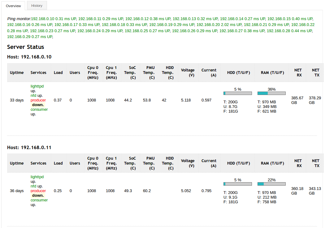
Now you should be able to access the web page from the gateway access network via http://name-or-ip-of-your-gateway/netstat/stat.php. The picture below shows a snippet of a correctly set up statistics script.
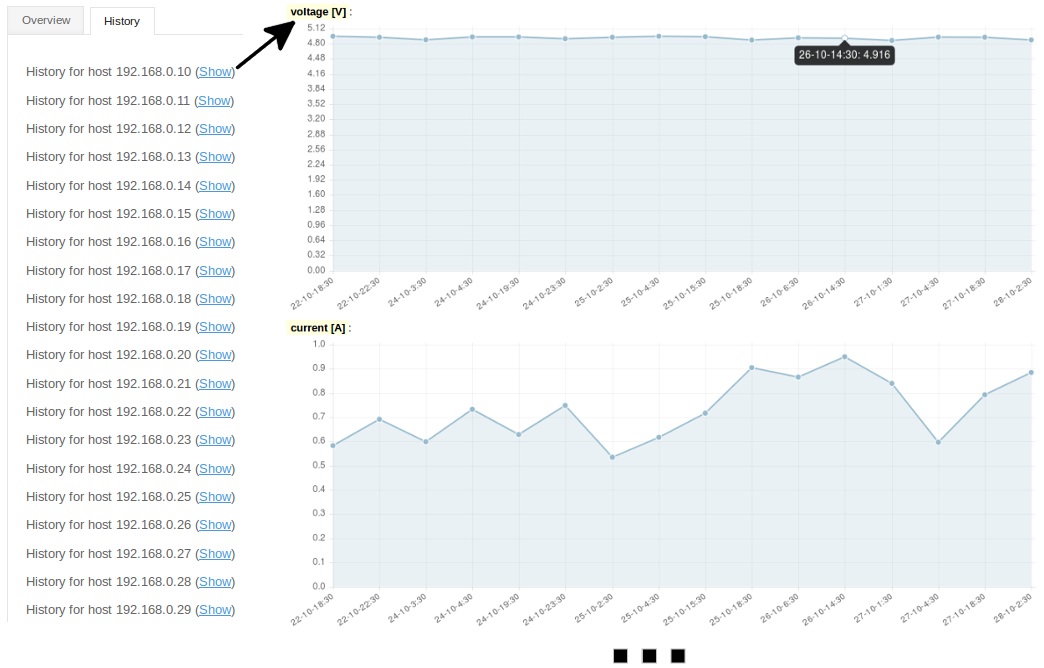
You will also be able to display a history page, where previous statistics of all individual devices will be listed, which will be vital if you are running long simulations. After selecting the script’s ‘History’ tab, as is depicted below, you can pick a specific Pi router and display it’s statistics history.
Step 7: Managing the realtime-logging daemon
This optional step familiarizes you with the ways to manage the operation of the realtime-logging daemon. By default, when using the provided pi-ssd-image (Download section), the realtime logging daemon is enabled and automatically starts.
This daemon, running on the individual Pis supplies the information for the near realtime-logging of Pi router status information by periodically querying the information and actively pushing the status-files onto the gateway-server. Another difference to the previously mentioned way of observing the network-status (Step 6) is the much smaller interval between updates.
In case you do not use this kind of fine-grained logging or you do not want the additional overhead caused by realtime-logging, you may deactivate it for the current session / permanently.
The daemon itself is modelled after the init-script-template of /etc/init.d/skeleton and therefore supports some common commands.
sudo service realtime_logging start
sudo service reatlime_logging stop
sudo service realtime_logging status
To disable/enable the daemon to automatically start on system startup, you may issue following commands.
cd /etc/init.d/ && sudo update-rc.d realtime_logging disable
cd /etc/init.d/ && sudo update-rc.d realtime_logging enable
man update-rc.d
Using disable/enable does NOT stop/start the realtime logging daemon (only at the next runlevel-change), either start/stop them yourself, change runlevel or reboot the Pi. In order to perform the operations on all Pis, we suggest using a script (e.g. runcommand.py of the provided
pi_scripts).
Note: You may consult the gateway_installation_guide from our Download section for additional information on how to install a visualization for observing emulations in near-realtime, and more detailed information about setting up the gateway-server itself.
continue to Quickstart: Your first Emulation using the provided Scripts